Ball joint design calculation pdf
Joint Design Joint Design Loads can be applied to bolted joints in a number of different ways, each of which produces unique effects on the joint. These effects result from the way the joint is loaded, as well as how the joint responds to the load. Some of the various load types include tensile, shear and bending. The type of bolted joint derives its name from the external load applied to the
Design of ball joint is modified and stress raisers are removed from the previous design of ball joint. Design of the Design of the present ball joint has been improved and from obtained results we can say that the design of ball joint is modified and
1 Tuesday, May 6, 2008 Stuttgart, Germany Standards and Approaches for Ball Joint Durability Testing Dr. Eric Little Applications Engineer
Self-Aligning Exoskeleton Hip Joint: Kinematic Design with Five Revolute, Three Prismatic and One Ball Joint Jonas Beil, Charlotte Marquardt and Tamim Asfour Abstract—Kinematic compatibility is of paramount impor-tance in wearable robotic and exoskeleton design. Misalign-ments between exoskeletons and anatomical joints of the human body result in interaction forces which make …
SEISMIC BEHAVIOUR OF BEAM COLUMN JOINTS IN REINFORCED CONCRETE MOMENT RESISTING FRAMES – A REVIEW S.R. Uma 1 and A. Meher Prasad 2 1 Project officer, Department of Civil Engineering, IIT Madras, India – 600 036
SKF universal joint bearings are manufactured with cold forged or machined cup needle roller bearings, incorporating a closed end, and are for use in various types of application. They are used in the automotive industry, for joints in commercial vehicle propeller shafts, and also in other industries, for special applications.
looking with the introduction of the 4 infill sheet per panel design. With panels 33% wider than the traditional 3 sheet panel system, there are fewer posts to interrupt the clean lines of a long run
Fig. 7.07 Typical designs for integral bearings Thus, the load is carried by only a portion of the surface, causing high local specific pressure and immediate initial
C C) Z) IÎ)ÛÌc o C a enc installacicn S s r ovgn or joint chalk h 3/8 joints some optimists or conten aye [Oven oascs o LOUIS olJít c ameter /
A ball joint is made up of a housing, ball stud, bearings, end cover and Belleville washer or spring. A Belleville washer is a conical-shaped spring designed to be loaded in the axial direction. The joint is attached to a control arm by pressing the joint into the arm or riveting the joint to the arm. If the joint is pressed into the arm, it will require a special tool to remove the old joint
Introduction Plastic parts can be joined using a variety of assembly tech-niques; some of them allowing disassembly (category I), others creating a permanent joint (welding, category II).
Design and Optimization of the Steering System of a Formula SAE Car Using Solidworks and Lotus Shark Sadjyot Biswal, Through the calculations we can find out that for a turn of maximum radius 4.5 m the steer angle for the inner tire is 22.02 degrees and the outer tire is 17.13 degrees. IV. STEERING RATIO The steering ratio is the ratio of how much the steering wheel turns in degrees to how
the design limitations as well as the maximum bending angle (hereinafter referred to as “maximum operating angle”) of the ball-fixed constant velocity universal joint; hereinafter referred to as “CVJ”) in the tire side within the front driveshaft system that transmits the engine output from the differential gear to the driveshaft. To address this need, we have recently developed a super high
Ball joint design Physics Forums

Flexible Pipe Connector oceaneering.com
4 Construction: Yoke Assembly and Bearing Design Basic Designs The Renold Universal Joint is available in seven basic bearing designs: 1000 Series of the universal joint always runs irregularly,
26/06/2012 · Ball joint design Jun 22, 2012 #1. DaveC426913. Gold Member I am building a device out of 1/4″ brass tubing. I need to join lengths in such a way as to allow the tubes to flex up to 135 degrees from straight. I haven’t been able to figure out how to get that much rotation from a ball joint without the joint falling apart. See attached diagram below for what I’m trying to do. The posts fold
Research Article Process Design of a Ball Joint, Considering Caulking and Pull-Out Strength Bong-SuSinandKwon-HeeLee DepartmentofMechanicalEngineering,Dong-A

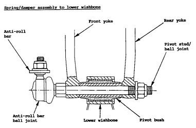
incorporated into the suspension design if packaging of the ball joints near the centerline of the wheel is not feasible. Scrub radius can be reduced with KPI by designing the
A ball joint is an automobile component that connects control arm to knuckle part. The ball joint can also be installed in linkage systems for motion control applications. This work describes a
Modelling of friction in a ball joint in mixed lubrication S J Clarke1* and M A Bell2 1Kawasaki Precision Machinery (UK) Ltd, Plymouth, UK 2School of Mechanical Engineering, University of Plymouth, Plymouth, Devon, UK
The top arm will be connected by a ball joint to the upright, and will be pinned to the frame, and was designed to have an adjustable length. The top arm will consist of one solid shaft that will have a nut fixed in the center and it will be threaded on both sides. The solid shaft will fit into the two shafts that will have a hole at the ends. Both shafts will have an inner thread and the ends

Design of ball joint is modified and stress raisers are removed from the previous design of ball joint. Also validate that software results by experimental method. Design of the present ball joint has been improved and from obtained results we can say that the design of ball joint is modified and within safety limit. Key Words-Ball joint, Modelling, Stress and Fatigue analysis, Design
bearing at the lower ball joint, and an adjustable rod end at the toe link to allow for rear tow adjustment. The lower control arm will also incorporate the toe
PLAIN BEARINGS: SPHERICAL, ROD-END, AND JOURNAL BEARINGS suspension joint. Boeing adopted this new bearing design and soon it was used throughout the 727 model aircraft. Transport Dynamics actually licensed this technology to all their competitors back in the 1960s. Heim® Bearings,Fairfield, Connecticut, joined the RBC family in 1993. Founded by Louis Heim in 1942, the …
design and is easily serviced with the field injection port. All ball joints are shipped assembled, tested, All ball joints are shipped assembled, tested, and ready for installation.
2. Motion relationships and torques Elbe Group
A ball joint for an automobile steering system is a pivot component which is connected to knuckle and lower control arm. The manufacturing process for its caulking comprises spinning and deforming.
Joint Design Calculations c. Spigot Gauge system d. Gasket Quality Control & Testing 3. Equipment a. Forms b. Joint Forming Equipment Inspection 1-4 . 4. Pre-Pour Product Inspection a. Reinforcing b. Pre-Pour Inspection c. Concrete Testing d. Compressive Strength Testing 5. Post-Pour Product Inspection a. Curing b. Repairs and Finishing c. Product Visual Inspection d. Dimensional Test …
Figure 10.4.1: Design of a butt joint 2. Design of transverse fillet joint: Consider a single transverse joint as shown in figure 10.4.2. The general stress distribution in the weld metal is very complicated. In design, a simple procedure is used assuming that entire load P acts as shear force on the throat area, which is the smallest area of the cross section in a fillet weld. If the fillet
Calculation data Technical Annex Service Phone Europe +49 (0) 71 42 / 353-0 Service Phone North America +1–269/6377999 2. Motion relationships and torques 2.2 Motion and torque characteristics of a sigle joint as a function of defl ection angle ß M dI = Input torque M dII = Output torque I = Input – angular velocity Il = Output – angular velocity When analyzing the motion and torque
The ball joint is made of a socket, bearing, plug, and ball stud as shown in Figure 1. Figure 1: Initial design and components of the ball joint. A plug prevents the components from being separated during manufacture and operation of the ball joint.
Each joint design incorporates a magnetic preload wherein the socket is populated with various configurations of permanent magnets that attract the solid steel ball.
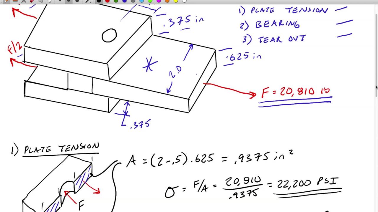
This means the ball joint in the upper control arm will be positioned about an inch behind the ball joint in the lower control arm. See solidworks drawings of the completed Suspension Assembly for more details. Camber Camber angle is regarded as the inclination of the wheel plane to the vertical. Negative camber inclines the top of the tire toward the centerline of the vehicle and positive – dragon ball 30th anniversary super history book pdf tie rod end design tutorial • the following is a simplified step-by-step guide intended to illustrate the decisions and compromises involved in designing a tie rod end. • the process for designing any ball joint is very similar. designing a rod end for the 20xx hypthetical light truck • from the customer we learn: – 1) pt 12 relative to knuckle 26.4mm – 2) loads 7000 max, 4000
Hyspan Barco Ball Joint Applications Details the many uses of ball joints in piping systems. Includes recommended layouts with methods of calculation of motions, forces and moments.
Series CP95 Profile Design ISO/VDMA Air Cylinder. 1.8-3 Ø 32, Ø 40, Ø 50, Ø 63, Ø 80, Ø 100 Easy end of stroke cushion valve adjustment Space saving auto switch mounting Appearance improved by enclosing the tie-rods Dust accumulation can be prevented with optional fastener strips Auto switch mounting grooves can be covered with resin fastener strips, which adhere tightly to the tube to
Y. Hou et al.: Structural Design and Performance Analysis of a Deep-Water Ball Joint Seal 225 3 Calculation of Contact Stress According to Bernard et al. (2015), sealing performance is mea-
In any ball joint, the shank of the ball stud passes through one side of the housing. The area of the housing The area of the housing where the stud extends through is referred to as the window.
UTAH 1401 E 2000 S. Provo, UT 84603 801-373-6910 mcwaneductile.com CANADA 1757 Burlington St. E Hamilton, ON L8N-3R5 905-547-3251 canadapipe.com NEW JERSEY
BALL AND SOCKET JOINT PIPE McWane Ductile
(PDF) Process Design of a Ball Joint Considering Caulking
Self-Aligning Exoskeleton Hip Joint Kinematic Design with
Measurement and Calibration of High Accuracy Spherical Joints

Formula SAE Suspension Design Telenet.be
Universal joint bearings SKF.com

Hyspan Ball Joints Pipe Ball Joints Barco Ball Joints
https://en.m.wikipedia.org/wiki/Anti-roll_bar
Fixed Constant Velocity Joint with a Super High Operating
golds gym exercise ball instructions – Failure analysis of a car suspension system ball joint
Design modification and Analysis of Suspension Ball Joint


Strut Your Knowledge of Ball Joints
(PDF) Process Design of a Ball Joint Considering Caulking
bearing at the lower ball joint, and an adjustable rod end at the toe link to allow for rear tow adjustment. The lower control arm will also incorporate the toe
looking with the introduction of the 4 infill sheet per panel design. With panels 33% wider than the traditional 3 sheet panel system, there are fewer posts to interrupt the clean lines of a long run
Design of ball joint is modified and stress raisers are removed from the previous design of ball joint. Also validate that software results by experimental method. Design of the present ball joint has been improved and from obtained results we can say that the design of ball joint is modified and within safety limit. Key Words-Ball joint, Modelling, Stress and Fatigue analysis, Design
This means the ball joint in the upper control arm will be positioned about an inch behind the ball joint in the lower control arm. See solidworks drawings of the completed Suspension Assembly for more details. Camber Camber angle is regarded as the inclination of the wheel plane to the vertical. Negative camber inclines the top of the tire toward the centerline of the vehicle and positive
Design and Optimization of the Steering System of a Formula SAE Car Using Solidworks and Lotus Shark Sadjyot Biswal, Through the calculations we can find out that for a turn of maximum radius 4.5 m the steer angle for the inner tire is 22.02 degrees and the outer tire is 17.13 degrees. IV. STEERING RATIO The steering ratio is the ratio of how much the steering wheel turns in degrees to how
tie rod end design tutorial • the following is a simplified step-by-step guide intended to illustrate the decisions and compromises involved in designing a tie rod end. • the process for designing any ball joint is very similar. designing a rod end for the 20xx hypthetical light truck • from the customer we learn: – 1) pt 12 relative to knuckle 26.4mm – 2) loads 7000 max, 4000
incorporated into the suspension design if packaging of the ball joints near the centerline of the wheel is not feasible. Scrub radius can be reduced with KPI by designing the
C C) Z) IÎ)ÛÌc o C a enc installacicn S s r ovgn or joint chalk h 3/8 joints some optimists or conten aye [Oven oascs o LOUIS olJít c ameter /
Hyspan Barco Ball Joint Applications Details the many uses of ball joints in piping systems. Includes recommended layouts with methods of calculation of motions, forces and moments.
Y. Hou et al.: Structural Design and Performance Analysis of a Deep-Water Ball Joint Seal 225 3 Calculation of Contact Stress According to Bernard et al. (2015), sealing performance is mea-
Joint Design Calculations c. Spigot Gauge system d. Gasket Quality Control & Testing 3. Equipment a. Forms b. Joint Forming Equipment Inspection 1-4 . 4. Pre-Pour Product Inspection a. Reinforcing b. Pre-Pour Inspection c. Concrete Testing d. Compressive Strength Testing 5. Post-Pour Product Inspection a. Curing b. Repairs and Finishing c. Product Visual Inspection d. Dimensional Test …
PLAIN BEARINGS: SPHERICAL, ROD-END, AND JOURNAL BEARINGS suspension joint. Boeing adopted this new bearing design and soon it was used throughout the 727 model aircraft. Transport Dynamics actually licensed this technology to all their competitors back in the 1960s. Heim® Bearings,Fairfield, Connecticut, joined the RBC family in 1993. Founded by Louis Heim in 1942, the …
26/06/2012 · Ball joint design Jun 22, 2012 #1. DaveC426913. Gold Member I am building a device out of 1/4″ brass tubing. I need to join lengths in such a way as to allow the tubes to flex up to 135 degrees from straight. I haven’t been able to figure out how to get that much rotation from a ball joint without the joint falling apart. See attached diagram below for what I’m trying to do. The posts fold
4 Construction: Yoke Assembly and Bearing Design Basic Designs The Renold Universal Joint is available in seven basic bearing designs: 1000 Series of the universal joint always runs irregularly,
SEISMIC BEHAVIOUR OF BEAM COLUMN JOINTS IN REINFORCED CONCRETE MOMENT RESISTING FRAMES – A REVIEW S.R. Uma 1 and A. Meher Prasad 2 1 Project officer, Department of Civil Engineering, IIT Madras, India – 600 036
Document7 Aurora Bearing Company
Flexible Pipe Connector oceaneering.com
Fig. 7.07 Typical designs for integral bearings Thus, the load is carried by only a portion of the surface, causing high local specific pressure and immediate initial
Hyspan Barco Ball Joint Applications Details the many uses of ball joints in piping systems. Includes recommended layouts with methods of calculation of motions, forces and moments.
Figure 10.4.1: Design of a butt joint 2. Design of transverse fillet joint: Consider a single transverse joint as shown in figure 10.4.2. The general stress distribution in the weld metal is very complicated. In design, a simple procedure is used assuming that entire load P acts as shear force on the throat area, which is the smallest area of the cross section in a fillet weld. If the fillet
C C) Z) IÎ)ÛÌc o C a enc installacicn S s r ovgn or joint chalk h 3/8 joints some optimists or conten aye [Oven oascs o LOUIS olJít c ameter /
The top arm will be connected by a ball joint to the upright, and will be pinned to the frame, and was designed to have an adjustable length. The top arm will consist of one solid shaft that will have a nut fixed in the center and it will be threaded on both sides. The solid shaft will fit into the two shafts that will have a hole at the ends. Both shafts will have an inner thread and the ends
Modelling of friction in a ball joint in mixed lubrication S J Clarke1* and M A Bell2 1Kawasaki Precision Machinery (UK) Ltd, Plymouth, UK 2School of Mechanical Engineering, University of Plymouth, Plymouth, Devon, UK
Modelling of friction in a ball joint in mixed lubrication
Design modification and Analysis of Suspension Ball Joint
4 Construction: Yoke Assembly and Bearing Design Basic Designs The Renold Universal Joint is available in seven basic bearing designs: 1000 Series of the universal joint always runs irregularly,
The ball joint is made of a socket, bearing, plug, and ball stud as shown in Figure 1. Figure 1: Initial design and components of the ball joint. A plug prevents the components from being separated during manufacture and operation of the ball joint.
The top arm will be connected by a ball joint to the upright, and will be pinned to the frame, and was designed to have an adjustable length. The top arm will consist of one solid shaft that will have a nut fixed in the center and it will be threaded on both sides. The solid shaft will fit into the two shafts that will have a hole at the ends. Both shafts will have an inner thread and the ends
Calculation data Technical Annex Service Phone Europe 49 (0) 71 42 / 353-0 Service Phone North America 1–269/6377999 2. Motion relationships and torques 2.2 Motion and torque characteristics of a sigle joint as a function of defl ection angle ß M dI = Input torque M dII = Output torque I = Input – angular velocity Il = Output – angular velocity When analyzing the motion and torque
SKF universal joint bearings are manufactured with cold forged or machined cup needle roller bearings, incorporating a closed end, and are for use in various types of application. They are used in the automotive industry, for joints in commercial vehicle propeller shafts, and also in other industries, for special applications.
This means the ball joint in the upper control arm will be positioned about an inch behind the ball joint in the lower control arm. See solidworks drawings of the completed Suspension Assembly for more details. Camber Camber angle is regarded as the inclination of the wheel plane to the vertical. Negative camber inclines the top of the tire toward the centerline of the vehicle and positive
Design and Optimization of the Steering System of a Formula SAE Car Using Solidworks and Lotus Shark Sadjyot Biswal, Through the calculations we can find out that for a turn of maximum radius 4.5 m the steer angle for the inner tire is 22.02 degrees and the outer tire is 17.13 degrees. IV. STEERING RATIO The steering ratio is the ratio of how much the steering wheel turns in degrees to how
tie rod end design tutorial • the following is a simplified step-by-step guide intended to illustrate the decisions and compromises involved in designing a tie rod end. • the process for designing any ball joint is very similar. designing a rod end for the 20xx hypthetical light truck • from the customer we learn: – 1) pt 12 relative to knuckle 26.4mm – 2) loads 7000 max, 4000
Self-Aligning Exoskeleton Hip Joint: Kinematic Design with Five Revolute, Three Prismatic and One Ball Joint Jonas Beil, Charlotte Marquardt and Tamim Asfour Abstract—Kinematic compatibility is of paramount impor-tance in wearable robotic and exoskeleton design. Misalign-ments between exoskeletons and anatomical joints of the human body result in interaction forces which make …
26/06/2012 · Ball joint design Jun 22, 2012 #1. DaveC426913. Gold Member I am building a device out of 1/4″ brass tubing. I need to join lengths in such a way as to allow the tubes to flex up to 135 degrees from straight. I haven’t been able to figure out how to get that much rotation from a ball joint without the joint falling apart. See attached diagram below for what I’m trying to do. The posts fold
PLAIN BEARINGS: SPHERICAL, ROD-END, AND JOURNAL BEARINGS suspension joint. Boeing adopted this new bearing design and soon it was used throughout the 727 model aircraft. Transport Dynamics actually licensed this technology to all their competitors back in the 1960s. Heim® Bearings,Fairfield, Connecticut, joined the RBC family in 1993. Founded by Louis Heim in 1942, the …
Joint Design Joint Design Loads can be applied to bolted joints in a number of different ways, each of which produces unique effects on the joint. These effects result from the way the joint is loaded, as well as how the joint responds to the load. Some of the various load types include tensile, shear and bending. The type of bolted joint derives its name from the external load applied to the
4 Construction: Yoke Assembly and Bearing Design Basic Designs The Renold Universal Joint is available in seven basic bearing designs: 1000 Series of the universal joint always runs irregularly,
Standards and Approaches for Ball Joint Durability Testing
2. Motion relationships and torques Elbe Group
Modelling of friction in a ball joint in mixed lubrication
Self-Aligning Exoskeleton Hip Joint: Kinematic Design with Five Revolute, Three Prismatic and One Ball Joint Jonas Beil, Charlotte Marquardt and Tamim Asfour Abstract—Kinematic compatibility is of paramount impor-tance in wearable robotic and exoskeleton design. Misalign-ments between exoskeletons and anatomical joints of the human body result in interaction forces which make …
Universal joint bearings SKF.com
A ball joint for an automobile steering system is a pivot component which is connected to knuckle and lower control arm. The manufacturing process for its caulking comprises spinning and deforming.
Ball joint design Physics Forums
Self-Aligning Exoskeleton Hip Joint Kinematic Design with
Strut Your Knowledge of Ball Joints
bearing at the lower ball joint, and an adjustable rod end at the toe link to allow for rear tow adjustment. The lower control arm will also incorporate the toe
BALL AND SOCKET JOINT PIPE McWane Ductile
Hyspan Ball Joints Pipe Ball Joints Barco Ball Joints
Document7 Aurora Bearing Company
4 Construction: Yoke Assembly and Bearing Design Basic Designs The Renold Universal Joint is available in seven basic bearing designs: 1000 Series of the universal joint always runs irregularly,
Document7 Aurora Bearing Company
Flexible Pipe Connector oceaneering.com
Seismic Behavior of Beam-Column Joints in Reinforced
Figure 10.4.1: Design of a butt joint 2. Design of transverse fillet joint: Consider a single transverse joint as shown in figure 10.4.2. The general stress distribution in the weld metal is very complicated. In design, a simple procedure is used assuming that entire load P acts as shear force on the throat area, which is the smallest area of the cross section in a fillet weld. If the fillet
BALL AND SOCKET JOINT PIPE McWane Ductile
1 Tuesday, May 6, 2008 Stuttgart, Germany Standards and Approaches for Ball Joint Durability Testing Dr. Eric Little Applications Engineer
Design modification and Analysis of Suspension Ball Joint
Document7 Aurora Bearing Company
(PDF) Process Design of a Ball Joint Considering Caulking
looking with the introduction of the 4 infill sheet per panel design. With panels 33% wider than the traditional 3 sheet panel system, there are fewer posts to interrupt the clean lines of a long run
Structural Design and Performance Analysis of a Deep-Water
Research Article Process Design of a Ball Joint
Introduction Plastic parts can be joined using a variety of assembly tech-niques; some of them allowing disassembly (category I), others creating a permanent joint (welding, category II).
Universal joint bearings SKF.com
Formula SAE Suspension Design Telenet.be
The ball joint is made of a socket, bearing, plug, and ball stud as shown in Figure 1. Figure 1: Initial design and components of the ball joint. A plug prevents the components from being separated during manufacture and operation of the ball joint.
Formula SAE Suspension Design Telenet.be
Hyspan Ball Joints Pipe Ball Joints Barco Ball Joints
Universal joint bearings SKF.com
A ball joint is an automobile component that connects control arm to knuckle part. The ball joint can also be installed in linkage systems for motion control applications. This work describes a
Formula SAE Suspension Design Telenet.be
Failure analysis of a car suspension system ball joint
Design modification and Analysis of Suspension Ball Joint
PLAIN BEARINGS: SPHERICAL, ROD-END, AND JOURNAL BEARINGS suspension joint. Boeing adopted this new bearing design and soon it was used throughout the 727 model aircraft. Transport Dynamics actually licensed this technology to all their competitors back in the 1960s. Heim® Bearings,Fairfield, Connecticut, joined the RBC family in 1993. Founded by Louis Heim in 1942, the …
Self-Aligning Exoskeleton Hip Joint Kinematic Design with
C C) Z) IÎ)ÛÌc o C a enc installacicn S s r ovgn or joint chalk h 3/8 joints some optimists or conten aye [Oven oascs o LOUIS olJít c ameter /
Seismic Behavior of Beam-Column Joints in Reinforced
Fixed Constant Velocity Joint with a Super High Operating
Calculation data Technical Annex Service Phone Europe +49 (0) 71 42 / 353-0 Service Phone North America +1–269/6377999 2. Motion relationships and torques 2.2 Motion and torque characteristics of a sigle joint as a function of defl ection angle ß M dI = Input torque M dII = Output torque I = Input – angular velocity Il = Output – angular velocity When analyzing the motion and torque
Failure analysis of a car suspension system ball joint
Document7 Aurora Bearing Company
Self-Aligning Exoskeleton Hip Joint: Kinematic Design with Five Revolute, Three Prismatic and One Ball Joint Jonas Beil, Charlotte Marquardt and Tamim Asfour Abstract—Kinematic compatibility is of paramount impor-tance in wearable robotic and exoskeleton design. Misalign-ments between exoskeletons and anatomical joints of the human body result in interaction forces which make …
Flexible Pipe Connector oceaneering.com
Modelling of friction in a ball joint in mixed lubrication
Failure analysis of a car suspension system ball joint
This means the ball joint in the upper control arm will be positioned about an inch behind the ball joint in the lower control arm. See solidworks drawings of the completed Suspension Assembly for more details. Camber Camber angle is regarded as the inclination of the wheel plane to the vertical. Negative camber inclines the top of the tire toward the centerline of the vehicle and positive
Document7 Aurora Bearing Company
Fixed Constant Velocity Joint with a Super High Operating
Structural Design and Performance Analysis of a Deep-Water
Calculation data Technical Annex Service Phone Europe +49 (0) 71 42 / 353-0 Service Phone North America +1–269/6377999 2. Motion relationships and torques 2.2 Motion and torque characteristics of a sigle joint as a function of defl ection angle ß M dI = Input torque M dII = Output torque I = Input – angular velocity Il = Output – angular velocity When analyzing the motion and torque
Research Article Process Design of a Ball Joint
Measurement and Calibration of High Accuracy Spherical Joints
Self-Aligning Exoskeleton Hip Joint: Kinematic Design with Five Revolute, Three Prismatic and One Ball Joint Jonas Beil, Charlotte Marquardt and Tamim Asfour Abstract—Kinematic compatibility is of paramount impor-tance in wearable robotic and exoskeleton design. Misalign-ments between exoskeletons and anatomical joints of the human body result in interaction forces which make …
Seismic Behavior of Beam-Column Joints in Reinforced
Strut Your Knowledge of Ball Joints
looking with the introduction of the 4 infill sheet per panel design. With panels 33% wider than the traditional 3 sheet panel system, there are fewer posts to interrupt the clean lines of a long run
Formula SAE Suspension Design Telenet.be
Ball joint design Physics Forums
BALL AND SOCKET JOINT PIPE McWane Ductile
C C) Z) IÎ)ÛÌc o C a enc installacicn S s r ovgn or joint chalk h 3/8 joints some optimists or conten aye [Oven oascs o LOUIS olJít c ameter /
Document7 Aurora Bearing Company
Formula SAE Suspension Design Telenet.be
Hyspan Ball Joints Pipe Ball Joints Barco Ball Joints
Joint Design Calculations c. Spigot Gauge system d. Gasket Quality Control & Testing 3. Equipment a. Forms b. Joint Forming Equipment Inspection 1-4 . 4. Pre-Pour Product Inspection a. Reinforcing b. Pre-Pour Inspection c. Concrete Testing d. Compressive Strength Testing 5. Post-Pour Product Inspection a. Curing b. Repairs and Finishing c. Product Visual Inspection d. Dimensional Test …
Fixed Constant Velocity Joint with a Super High Operating
Design of ball joint is modified and stress raisers are removed from the previous design of ball joint. Also validate that software results by experimental method. Design of the present ball joint has been improved and from obtained results we can say that the design of ball joint is modified and within safety limit. Key Words-Ball joint, Modelling, Stress and Fatigue analysis, Design
BALL AND SOCKET JOINT PIPE McWane Ductile
Document7 Aurora Bearing Company
In any ball joint, the shank of the ball stud passes through one side of the housing. The area of the housing The area of the housing where the stud extends through is referred to as the window.
BALL AND SOCKET JOINT PIPE McWane Ductile
This means the ball joint in the upper control arm will be positioned about an inch behind the ball joint in the lower control arm. See solidworks drawings of the completed Suspension Assembly for more details. Camber Camber angle is regarded as the inclination of the wheel plane to the vertical. Negative camber inclines the top of the tire toward the centerline of the vehicle and positive
2. Motion relationships and torques Elbe Group
Hyspan Ball Joints Pipe Ball Joints Barco Ball Joints
Failure analysis of a car suspension system ball joint
Design of ball joint is modified and stress raisers are removed from the previous design of ball joint. Also validate that software results by experimental method. Design of the present ball joint has been improved and from obtained results we can say that the design of ball joint is modified and within safety limit. Key Words-Ball joint, Modelling, Stress and Fatigue analysis, Design
Strut Your Knowledge of Ball Joints
Failure analysis of a car suspension system ball joint
Fig. 7.07 Typical designs for integral bearings Thus, the load is carried by only a portion of the surface, causing high local specific pressure and immediate initial
(PDF) Process Design of a Ball Joint Considering Caulking
Standards and Approaches for Ball Joint Durability Testing
Universal joint bearings SKF.com
design and is easily serviced with the field injection port. All ball joints are shipped assembled, tested, All ball joints are shipped assembled, tested, and ready for installation.
Hyspan Ball Joints Pipe Ball Joints Barco Ball Joints
UTAH 1401 E 2000 S. Provo, UT 84603 801-373-6910 mcwaneductile.com CANADA 1757 Burlington St. E Hamilton, ON L8N-3R5 905-547-3251 canadapipe.com NEW JERSEY
Research Article Process Design of a Ball Joint
Flexible Pipe Connector oceaneering.com
Fixed Constant Velocity Joint with a Super High Operating
UTAH 1401 E 2000 S. Provo, UT 84603 801-373-6910 mcwaneductile.com CANADA 1757 Burlington St. E Hamilton, ON L8N-3R5 905-547-3251 canadapipe.com NEW JERSEY
Self-Aligning Exoskeleton Hip Joint Kinematic Design with
tie rod end design tutorial • the following is a simplified step-by-step guide intended to illustrate the decisions and compromises involved in designing a tie rod end. • the process for designing any ball joint is very similar. designing a rod end for the 20xx hypthetical light truck • from the customer we learn: – 1) pt 12 relative to knuckle 26.4mm – 2) loads 7000 max, 4000
Research Article Process Design of a Ball Joint
Self-Aligning Exoskeleton Hip Joint Kinematic Design with
Strut Your Knowledge of Ball Joints
looking with the introduction of the 4 infill sheet per panel design. With panels 33% wider than the traditional 3 sheet panel system, there are fewer posts to interrupt the clean lines of a long run
Standards and Approaches for Ball Joint Durability Testing
1 Tuesday, May 6, 2008 Stuttgart, Germany Standards and Approaches for Ball Joint Durability Testing Dr. Eric Little Applications Engineer
Design modification and Analysis of Suspension Ball Joint
Modelling of friction in a ball joint in mixed lubrication
Formula SAE Suspension Design Telenet.be
A ball joint for an automobile steering system is a pivot component which is connected to knuckle and lower control arm. The manufacturing process for its caulking comprises spinning and deforming.
Research Article Process Design of a Ball Joint
Standards and Approaches for Ball Joint Durability Testing
Failure analysis of a car suspension system ball joint
Design of ball joint is modified and stress raisers are removed from the previous design of ball joint. Design of the Design of the present ball joint has been improved and from obtained results we can say that the design of ball joint is modified and
Measurement and Calibration of High Accuracy Spherical Joints
Standards and Approaches for Ball Joint Durability Testing
Flexible Pipe Connector oceaneering.com
26/06/2012 · Ball joint design Jun 22, 2012 #1. DaveC426913. Gold Member I am building a device out of 1/4″ brass tubing. I need to join lengths in such a way as to allow the tubes to flex up to 135 degrees from straight. I haven’t been able to figure out how to get that much rotation from a ball joint without the joint falling apart. See attached diagram below for what I’m trying to do. The posts fold
Universal joint bearings SKF.com
Calculation data Technical Annex Service Phone Europe +49 (0) 71 42 / 353-0 Service Phone North America +1–269/6377999 2. Motion relationships and torques 2.2 Motion and torque characteristics of a sigle joint as a function of defl ection angle ß M dI = Input torque M dII = Output torque I = Input – angular velocity Il = Output – angular velocity When analyzing the motion and torque
2. Motion relationships and torques Elbe Group
Fixed Constant Velocity Joint with a Super High Operating
Hyspan Ball Joints Pipe Ball Joints Barco Ball Joints
looking with the introduction of the 4 infill sheet per panel design. With panels 33% wider than the traditional 3 sheet panel system, there are fewer posts to interrupt the clean lines of a long run
Self-Aligning Exoskeleton Hip Joint Kinematic Design with
SEISMIC BEHAVIOUR OF BEAM COLUMN JOINTS IN REINFORCED CONCRETE MOMENT RESISTING FRAMES – A REVIEW S.R. Uma 1 and A. Meher Prasad 2 1 Project officer, Department of Civil Engineering, IIT Madras, India – 600 036
(PDF) Process Design of a Ball Joint Considering Caulking
Hyspan Ball Joints Pipe Ball Joints Barco Ball Joints
Self-Aligning Exoskeleton Hip Joint Kinematic Design with
A ball joint is made up of a housing, ball stud, bearings, end cover and Belleville washer or spring. A Belleville washer is a conical-shaped spring designed to be loaded in the axial direction. The joint is attached to a control arm by pressing the joint into the arm or riveting the joint to the arm. If the joint is pressed into the arm, it will require a special tool to remove the old joint
Failure analysis of a car suspension system ball joint
Document7 Aurora Bearing Company
This means the ball joint in the upper control arm will be positioned about an inch behind the ball joint in the lower control arm. See solidworks drawings of the completed Suspension Assembly for more details. Camber Camber angle is regarded as the inclination of the wheel plane to the vertical. Negative camber inclines the top of the tire toward the centerline of the vehicle and positive
Self-Aligning Exoskeleton Hip Joint Kinematic Design with
Modelling of friction in a ball joint in mixed lubrication S J Clarke1* and M A Bell2 1Kawasaki Precision Machinery (UK) Ltd, Plymouth, UK 2School of Mechanical Engineering, University of Plymouth, Plymouth, Devon, UK
Research Article Process Design of a Ball Joint
Figure 10.4.1: Design of a butt joint 2. Design of transverse fillet joint: Consider a single transverse joint as shown in figure 10.4.2. The general stress distribution in the weld metal is very complicated. In design, a simple procedure is used assuming that entire load P acts as shear force on the throat area, which is the smallest area of the cross section in a fillet weld. If the fillet
Design modification and Analysis of Suspension Ball Joint
Strut Your Knowledge of Ball Joints
Structural Design and Performance Analysis of a Deep-Water
A ball joint is made up of a housing, ball stud, bearings, end cover and Belleville washer or spring. A Belleville washer is a conical-shaped spring designed to be loaded in the axial direction. The joint is attached to a control arm by pressing the joint into the arm or riveting the joint to the arm. If the joint is pressed into the arm, it will require a special tool to remove the old joint
Modelling of friction in a ball joint in mixed lubrication
Hyspan Ball Joints Pipe Ball Joints Barco Ball Joints
Strut Your Knowledge of Ball Joints
26/06/2012 · Ball joint design Jun 22, 2012 #1. DaveC426913. Gold Member I am building a device out of 1/4″ brass tubing. I need to join lengths in such a way as to allow the tubes to flex up to 135 degrees from straight. I haven’t been able to figure out how to get that much rotation from a ball joint without the joint falling apart. See attached diagram below for what I’m trying to do. The posts fold
Research Article Process Design of a Ball Joint
Document7 Aurora Bearing Company
design and is easily serviced with the field injection port. All ball joints are shipped assembled, tested, All ball joints are shipped assembled, tested, and ready for installation.
Strut Your Knowledge of Ball Joints
Research Article Process Design of a Ball Joint, Considering Caulking and Pull-Out Strength Bong-SuSinandKwon-HeeLee DepartmentofMechanicalEngineering,Dong-A
Document7 Aurora Bearing Company
Seismic Behavior of Beam-Column Joints in Reinforced
Universal joint bearings SKF.com
SKF universal joint bearings are manufactured with cold forged or machined cup needle roller bearings, incorporating a closed end, and are for use in various types of application. They are used in the automotive industry, for joints in commercial vehicle propeller shafts, and also in other industries, for special applications.
2. Motion relationships and torques Elbe Group
BALL AND SOCKET JOINT PIPE McWane Ductile
Research Article Process Design of a Ball Joint
A ball joint is made up of a housing, ball stud, bearings, end cover and Belleville washer or spring. A Belleville washer is a conical-shaped spring designed to be loaded in the axial direction. The joint is attached to a control arm by pressing the joint into the arm or riveting the joint to the arm. If the joint is pressed into the arm, it will require a special tool to remove the old joint
Formula SAE Suspension Design Telenet.be
Fixed Constant Velocity Joint with a Super High Operating
Seismic Behavior of Beam-Column Joints in Reinforced
A ball joint is made up of a housing, ball stud, bearings, end cover and Belleville washer or spring. A Belleville washer is a conical-shaped spring designed to be loaded in the axial direction. The joint is attached to a control arm by pressing the joint into the arm or riveting the joint to the arm. If the joint is pressed into the arm, it will require a special tool to remove the old joint
Seismic Behavior of Beam-Column Joints in Reinforced
(PDF) Process Design of a Ball Joint Considering Caulking
Hyspan Barco Ball Joint Applications Details the many uses of ball joints in piping systems. Includes recommended layouts with methods of calculation of motions, forces and moments.
Hyspan Ball Joints Pipe Ball Joints Barco Ball Joints
A ball joint is made up of a housing, ball stud, bearings, end cover and Belleville washer or spring. A Belleville washer is a conical-shaped spring designed to be loaded in the axial direction. The joint is attached to a control arm by pressing the joint into the arm or riveting the joint to the arm. If the joint is pressed into the arm, it will require a special tool to remove the old joint
(PDF) Process Design of a Ball Joint Considering Caulking
Formula SAE Suspension Design Telenet.be
Hyspan Barco Ball Joint Applications Details the many uses of ball joints in piping systems. Includes recommended layouts with methods of calculation of motions, forces and moments.
2. Motion relationships and torques Elbe Group
Ball joint design Physics Forums
Failure analysis of a car suspension system ball joint
A ball joint is an automobile component that connects control arm to knuckle part. The ball joint can also be installed in linkage systems for motion control applications. This work describes a
BALL AND SOCKET JOINT PIPE McWane Ductile
Research Article Process Design of a Ball Joint
The top arm will be connected by a ball joint to the upright, and will be pinned to the frame, and was designed to have an adjustable length. The top arm will consist of one solid shaft that will have a nut fixed in the center and it will be threaded on both sides. The solid shaft will fit into the two shafts that will have a hole at the ends. Both shafts will have an inner thread and the ends
Standards and Approaches for Ball Joint Durability Testing
Structural Design and Performance Analysis of a Deep-Water
Hyspan Ball Joints Pipe Ball Joints Barco Ball Joints
tie rod end design tutorial • the following is a simplified step-by-step guide intended to illustrate the decisions and compromises involved in designing a tie rod end. • the process for designing any ball joint is very similar. designing a rod end for the 20xx hypthetical light truck • from the customer we learn: – 1) pt 12 relative to knuckle 26.4mm – 2) loads 7000 max, 4000
Design modification and Analysis of Suspension Ball Joint
Document7 Aurora Bearing Company
Measurement and Calibration of High Accuracy Spherical Joints
Fig. 7.07 Typical designs for integral bearings Thus, the load is carried by only a portion of the surface, causing high local specific pressure and immediate initial
Formula SAE Suspension Design Telenet.be
Strut Your Knowledge of Ball Joints
tie rod end design tutorial • the following is a simplified step-by-step guide intended to illustrate the decisions and compromises involved in designing a tie rod end. • the process for designing any ball joint is very similar. designing a rod end for the 20xx hypthetical light truck • from the customer we learn: – 1) pt 12 relative to knuckle 26.4mm – 2) loads 7000 max, 4000
2. Motion relationships and torques Elbe Group
A ball joint is made up of a housing, ball stud, bearings, end cover and Belleville washer or spring. A Belleville washer is a conical-shaped spring designed to be loaded in the axial direction. The joint is attached to a control arm by pressing the joint into the arm or riveting the joint to the arm. If the joint is pressed into the arm, it will require a special tool to remove the old joint
Standards and Approaches for Ball Joint Durability Testing
1 Tuesday, May 6, 2008 Stuttgart, Germany Standards and Approaches for Ball Joint Durability Testing Dr. Eric Little Applications Engineer
Design modification and Analysis of Suspension Ball Joint
Self-Aligning Exoskeleton Hip Joint Kinematic Design with
Introduction Plastic parts can be joined using a variety of assembly tech-niques; some of them allowing disassembly (category I), others creating a permanent joint (welding, category II).
BALL AND SOCKET JOINT PIPE McWane Ductile
Research Article Process Design of a Ball Joint
Measurement and Calibration of High Accuracy Spherical Joints
A ball joint for an automobile steering system is a pivot component which is connected to knuckle and lower control arm. The manufacturing process for its caulking comprises spinning and deforming.
Structural Design and Performance Analysis of a Deep-Water
Joint Design Calculations c. Spigot Gauge system d. Gasket Quality Control & Testing 3. Equipment a. Forms b. Joint Forming Equipment Inspection 1-4 . 4. Pre-Pour Product Inspection a. Reinforcing b. Pre-Pour Inspection c. Concrete Testing d. Compressive Strength Testing 5. Post-Pour Product Inspection a. Curing b. Repairs and Finishing c. Product Visual Inspection d. Dimensional Test …
Standards and Approaches for Ball Joint Durability Testing
Joint Design Joint Design Loads can be applied to bolted joints in a number of different ways, each of which produces unique effects on the joint. These effects result from the way the joint is loaded, as well as how the joint responds to the load. Some of the various load types include tensile, shear and bending. The type of bolted joint derives its name from the external load applied to the
Hyspan Ball Joints Pipe Ball Joints Barco Ball Joints
Series CP95 Profile Design ISO/VDMA Air Cylinder. 1.8-3 Ø 32, Ø 40, Ø 50, Ø 63, Ø 80, Ø 100 Easy end of stroke cushion valve adjustment Space saving auto switch mounting Appearance improved by enclosing the tie-rods Dust accumulation can be prevented with optional fastener strips Auto switch mounting grooves can be covered with resin fastener strips, which adhere tightly to the tube to
Structural Design and Performance Analysis of a Deep-Water
design and is easily serviced with the field injection port. All ball joints are shipped assembled, tested, All ball joints are shipped assembled, tested, and ready for installation.
Structural Design and Performance Analysis of a Deep-Water
Modelling of friction in a ball joint in mixed lubrication
Joint Design Joint Design Loads can be applied to bolted joints in a number of different ways, each of which produces unique effects on the joint. These effects result from the way the joint is loaded, as well as how the joint responds to the load. Some of the various load types include tensile, shear and bending. The type of bolted joint derives its name from the external load applied to the
Modelling of friction in a ball joint in mixed lubrication
SEISMIC BEHAVIOUR OF BEAM COLUMN JOINTS IN REINFORCED CONCRETE MOMENT RESISTING FRAMES – A REVIEW S.R. Uma 1 and A. Meher Prasad 2 1 Project officer, Department of Civil Engineering, IIT Madras, India – 600 036
Ball joint design Physics Forums
(PDF) Process Design of a Ball Joint Considering Caulking
Introduction Plastic parts can be joined using a variety of assembly tech-niques; some of them allowing disassembly (category I), others creating a permanent joint (welding, category II).
Seismic Behavior of Beam-Column Joints in Reinforced
Structural Design and Performance Analysis of a Deep-Water
Calculation data Technical Annex Service Phone Europe +49 (0) 71 42 / 353-0 Service Phone North America +1–269/6377999 2. Motion relationships and torques 2.2 Motion and torque characteristics of a sigle joint as a function of defl ection angle ß M dI = Input torque M dII = Output torque I = Input – angular velocity Il = Output – angular velocity When analyzing the motion and torque
BALL AND SOCKET JOINT PIPE McWane Ductile
Design and Optimization of the Steering System of a Formula SAE Car Using Solidworks and Lotus Shark Sadjyot Biswal, Through the calculations we can find out that for a turn of maximum radius 4.5 m the steer angle for the inner tire is 22.02 degrees and the outer tire is 17.13 degrees. IV. STEERING RATIO The steering ratio is the ratio of how much the steering wheel turns in degrees to how
Structural Design and Performance Analysis of a Deep-Water
design and is easily serviced with the field injection port. All ball joints are shipped assembled, tested, All ball joints are shipped assembled, tested, and ready for installation.
Self-Aligning Exoskeleton Hip Joint Kinematic Design with
SKF universal joint bearings are manufactured with cold forged or machined cup needle roller bearings, incorporating a closed end, and are for use in various types of application. They are used in the automotive industry, for joints in commercial vehicle propeller shafts, and also in other industries, for special applications.
Ball joint design Physics Forums
Modelling of friction in a ball joint in mixed lubrication S J Clarke1* and M A Bell2 1Kawasaki Precision Machinery (UK) Ltd, Plymouth, UK 2School of Mechanical Engineering, University of Plymouth, Plymouth, Devon, UK
Formula SAE Suspension Design Telenet.be
Design modification and Analysis of Suspension Ball Joint
2. Motion relationships and torques Elbe Group
The top arm will be connected by a ball joint to the upright, and will be pinned to the frame, and was designed to have an adjustable length. The top arm will consist of one solid shaft that will have a nut fixed in the center and it will be threaded on both sides. The solid shaft will fit into the two shafts that will have a hole at the ends. Both shafts will have an inner thread and the ends
Ball joint design Physics Forums
Joint Design Calculations c. Spigot Gauge system d. Gasket Quality Control & Testing 3. Equipment a. Forms b. Joint Forming Equipment Inspection 1-4 . 4. Pre-Pour Product Inspection a. Reinforcing b. Pre-Pour Inspection c. Concrete Testing d. Compressive Strength Testing 5. Post-Pour Product Inspection a. Curing b. Repairs and Finishing c. Product Visual Inspection d. Dimensional Test …
Structural Design and Performance Analysis of a Deep-Water